How one of Cape May’s earliest beach homes survived storms, relocation, and time to stand tall once again
How one of Cape May’s earliest beach homes survived storms, relocation, and time to stand tall once again
This article was written by Nate Eldon for FineHomeBuilding.com on June 2024
Structural steel and strong connections help a raised floor resist high winds and water.
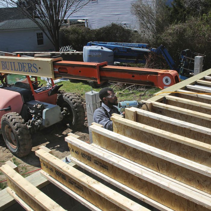
Building the first-floor addition to this seaside home included the installation of three steel I-beams to restrain the tops of the walls and keep them from toppling in a flood, and also to carry the load from the floor system, walls, and roof above to the foundation. Builder Nate Eldon walks through the process of prepping the foundation for the steel beams, setting the beams in place, adding shims to level the beams, and tying the floor system together with welded and bolted connections.
Cape May in New Jersey is the country’s oldest seaside resort, hosting vacationers from Philadelphia and the surrounding area starting in the mid-18th century. Despite decades of coastal storms, much of the Victorian architecture is still here, making Cape May second only to San Francisco for its collection of highly ornate wood-frame buildings from the 1800s. My firm does a lot of renovation work on these old houses, which usually involves adding on to the original structure in the form of dormers, add-a-levels, and rear additions.
Even though the houses we work on are old, anything new (and much of the old) must comply with modern building codes and Cape May’s strict zoning rules, which regulate any work that alters a home’s exterior. But most importantly, the houses we work on that are this close to the shore must withstand hurricane-force winds and be elevated to prevent damage from flooding.

One of our recent projects was an extensive renovation and addition to a Victorian-era house a couple blocks from the shore. The original portion of the house was built in the 1890s in South Cape May, a community so flood-prone it was abandoned in 1945. Records indicate that the home was moved one mile north to Cape May in the 1920s, likely by teams of horses. There were a few renovations of varying quality since then.
Floors joists, exterior walls, and beams had been compromised by adding bathrooms and altering the floor plan and exterior. The structural deficiencies and code-required improvements would be part of an extensive renovation that included a new two-story addition on the rear of the house. This article shows how we build a sturdy floor system above flood elevation that’s well-connected to its foundation. This is one of the most critical parts of a home built to withstand high water and punishing winds.
The home’s existing foundation is brick and the basement is part of the original living space. Part of our extensive renovation would be to remove any high-value basement finishes that could be damaged from flooding and replace them with more water-resistant materials. The basement would be a convenient and expansive space in which to store bikes, beach gear, and outdoor furniture.
We also had to raise electrical service and mechanical equipment above the design flood elevation (DFE), which is meant to keep HVAC and electrical components—and the floor system—above water during a severe flood. For this house and much of Cape May, the DFE is 101/2 ft., which is 21/2 ft. above the base flood elevation (BFE) of 8 ft. Flood maps assume that there’s a 1% chance of a flood equaling or exceeding the BFE in a given year.
The BFE for different areas can be found on FEMA’s website. DFE is determined by the municipality and is higher than BFE to minimize damage from flooding. Flood elevations are based on historical record, but they’ve been raised in recent years to compensate for the greater regularity of severe coastal storms. Local officials can help determine the DFE where you’re building.
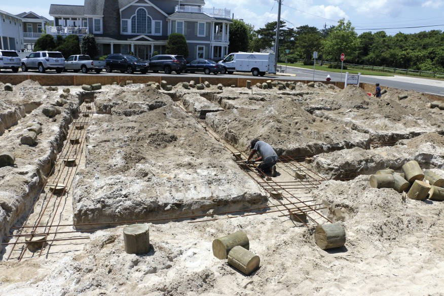
The rear addition’s foundation has steel-reinforced 8-in. block walls and piers built on reinforced concrete footings on top of treated-wood piers driven into the sand. The sections of framed walls between the block masonry are designed to give way during flooding. This equalizes water pressure on the inside and outside to keep the house standing during floods. Flood vents in the older parts of the house work similarly.
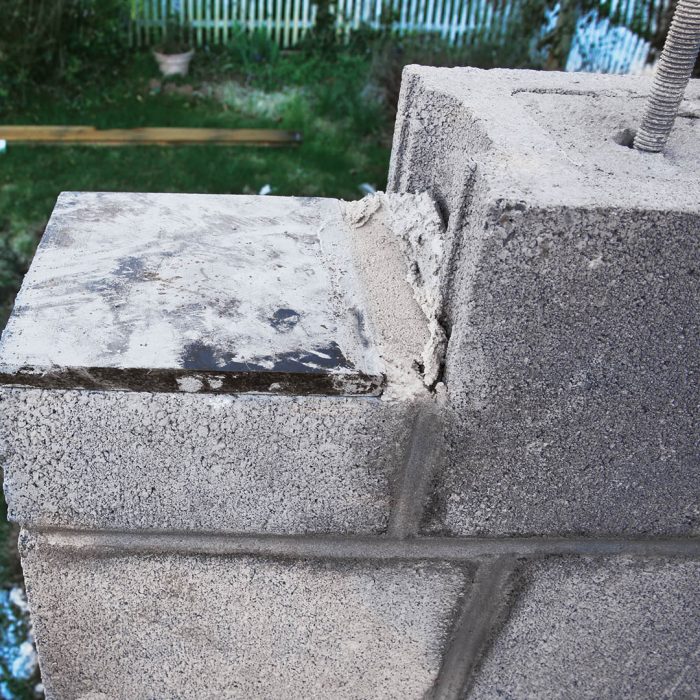
1.) Transition to SteelThe steel I-beams are connected to the foundation with steel plates, called embed plates. The 8-in. by 8-in. plates have steel legs welded to the underside that are grouted into the block walls by the masons who lay the block. The I-beams will be welded to the plates later. |
 |
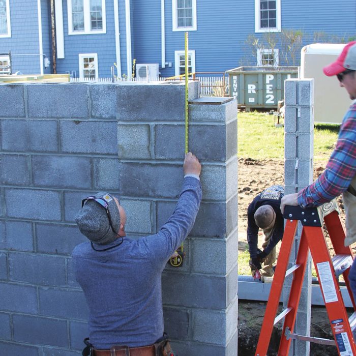 |
2.) Check the HeightThe 2×6 mudsill plate that will sit on top of the steel I-beam is designed to be flush with the top of the floor joists to receive the floor sheathing. Steel shims welded on top of the embed plates will bring the sill plate flush with the top of the floor joists and allow the sill to be leveled. |
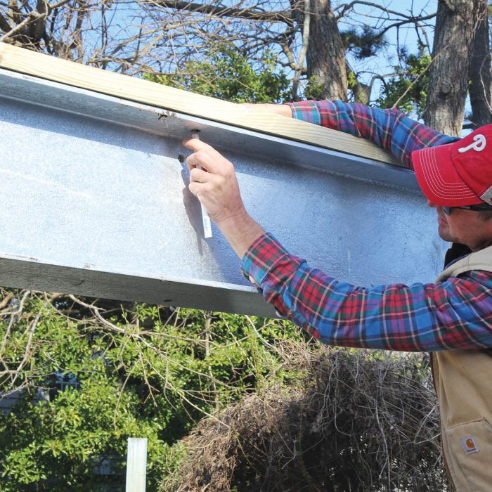
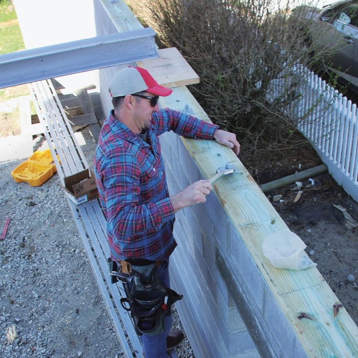
3.) Prep for PlatesDrilling holes in heavy steel on-site is time consuming, so instead we have the metal fabricator drill the components. This allows us to more easily attach wood plates and nailers to the steel I-beams and columns. |
 |
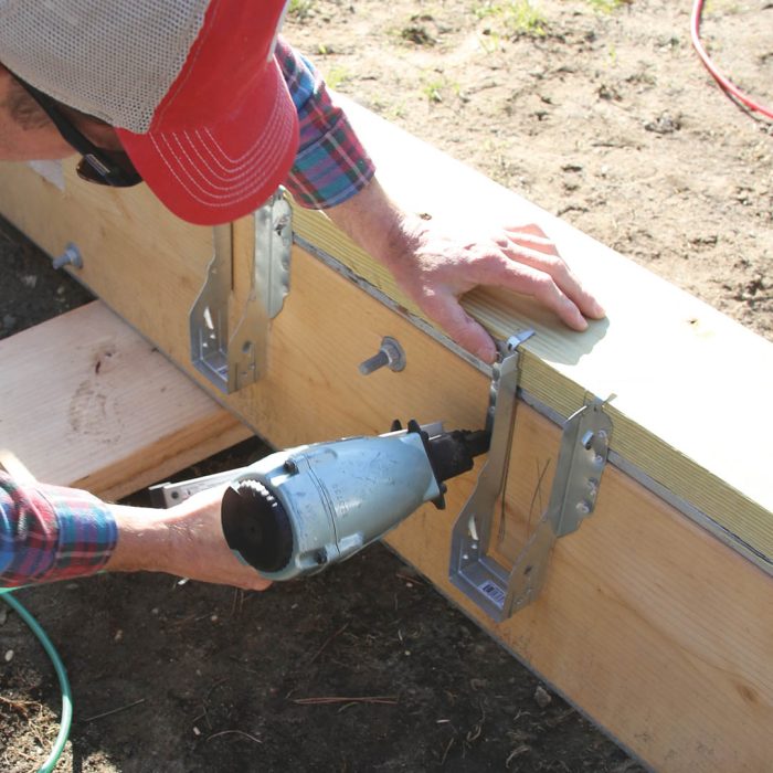 |
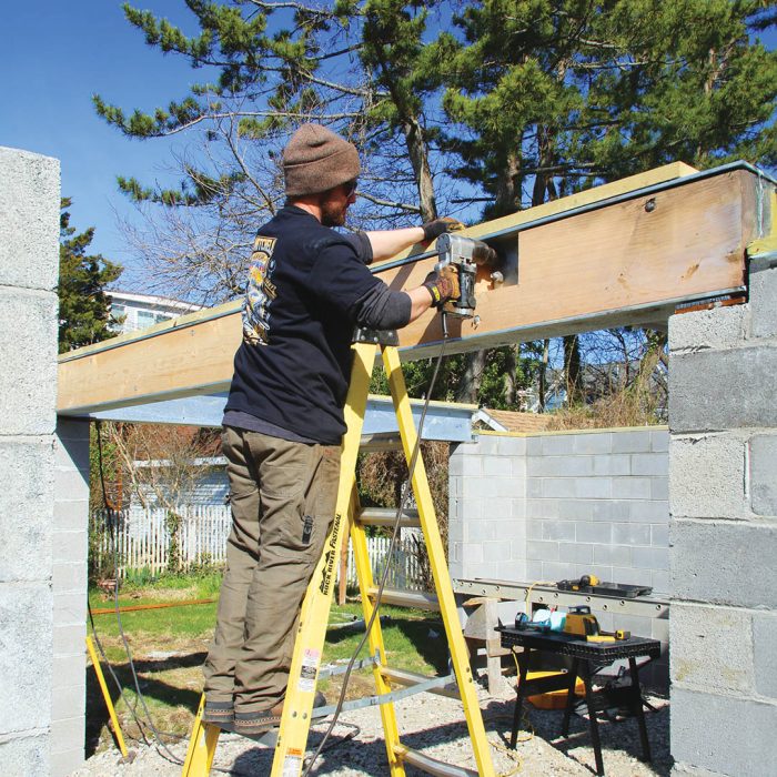
4.) Build Beams on the GroundThe steel I-beam that recieves the joists has a web about 11-1⁄2 in. tall. We pad out the pre-drilled web by bolting a pair of 2x12s to both sides, and then attach the face-mount I-joist hangers at 16 in. on-center with a connector nailer. |
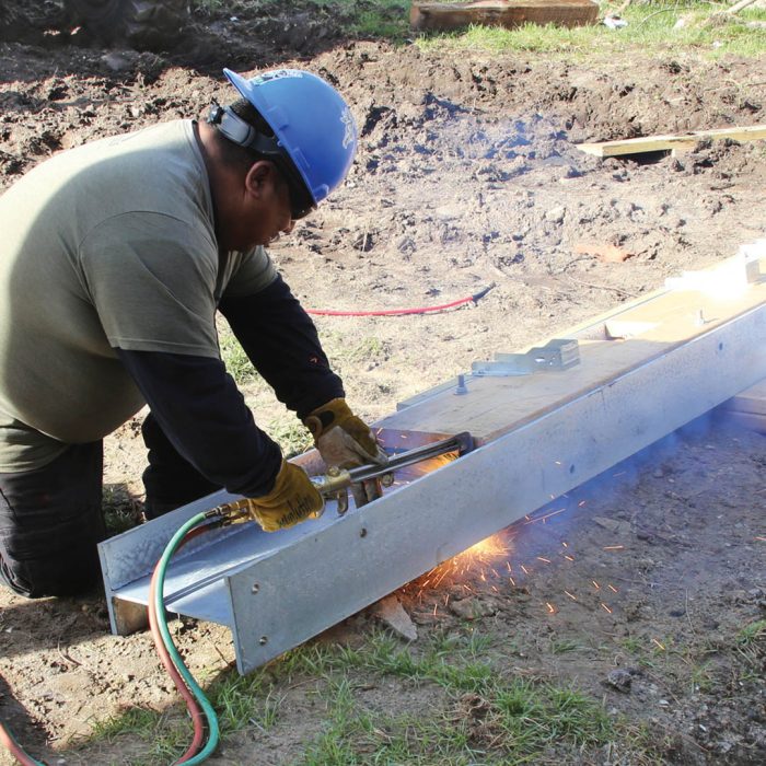
5.) Field-ModifyWhen we went to pad out the I-beam’s steel web with lumber for hangers, we realized the fabricator had made the beam too long. Instead of sending it back to the shop, the installation crew used an oxy-acetylene torch to trim the beam on-site. |
 |
In both our renovation and new-construction projects, structural steel is increasingly common for beams and headers for several reasons. Steel is much stronger than wood or engineered lumber of the same depth, allowing us to tuck flush beams into shallow assemblies and still carry big loads. It also lets us span longer distances for expansive rooms and extra wide window and door openings.
In areas with height restrictions and an amazing water view like Cape May, designers and clients want to maximize a home’s interior volume, and the thinner steel beams are less intrusive on views and living spaces. In addition, our projects sometimes use steel moment frames, which are basically steel rectangles or “U” shapes bolted together to help the building resist wind and shear loads.
In our new-home builds and renovations, the project architect works with an engineer to specify the steel- and wood-frame assemblies as part of their plan set. As GC, I work with a steel fabrication shop to have the parts made and assembled on-site. Generally it takes a few weeks for them to make the parts and schedule the job-site installation. Depending on the complexity, it may take a few hours to a few days to install a home’s steel work. Setting the steel beams and connecting them took a few hours on this project. It took a few hours more for my crew and me to frame and sheath the I-joist floor.
The steel I-beams that span the large openings in the foundation walls restrain the tops of the walls to keep them from toppling in a flood and also carry the load from the floor system, walls, and roof above to the foundation. An additional steel I-beam near the center of the floor continues a load path from the upstairs.
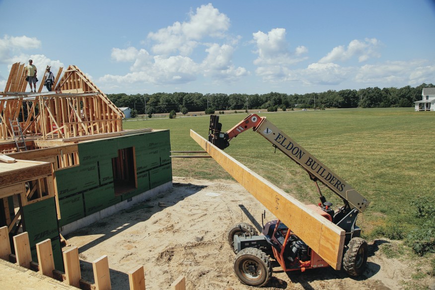
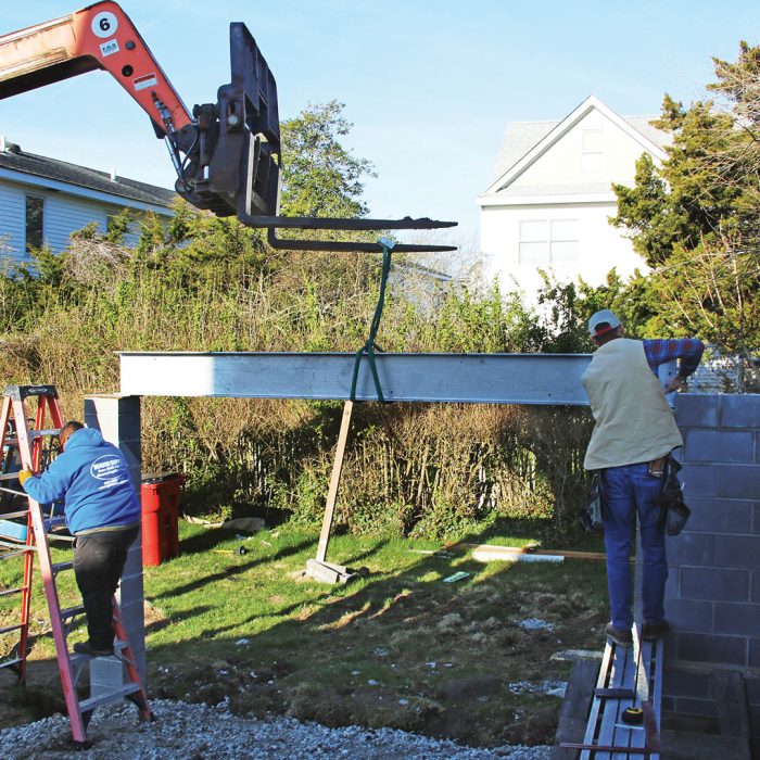
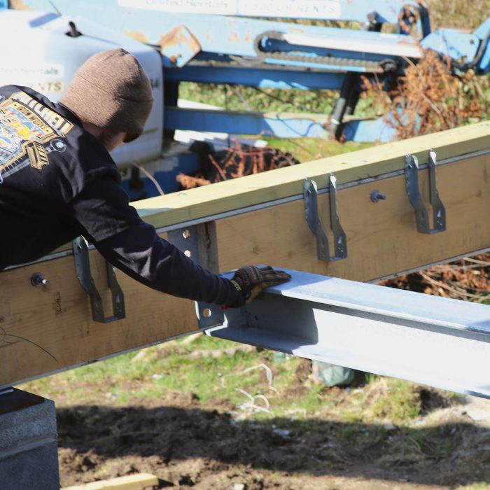
1.) Set One Side of a CornerA telehandler or crane is needed for lifting the steel components. We use a telehandler to help the steel fabricators set and level the steel I-beam that sits parallel to the floor joists. This 12-ft. 8-in. beam weighs more than 300 lb. |
 |
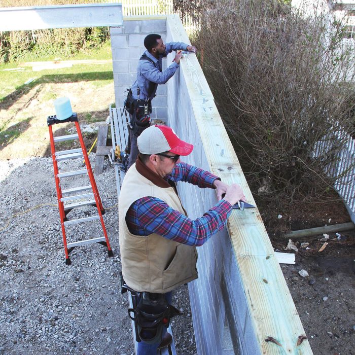 |
2.) Mark the MudsillPressure-treated mudsills connect the floor joists to the block foundation. While the steel crew prepares to lift and place the beam that receives the floor joists on the opposite side, we drill the mudsills for the 1⁄2-in. anchor bolts and lay out the joists. |
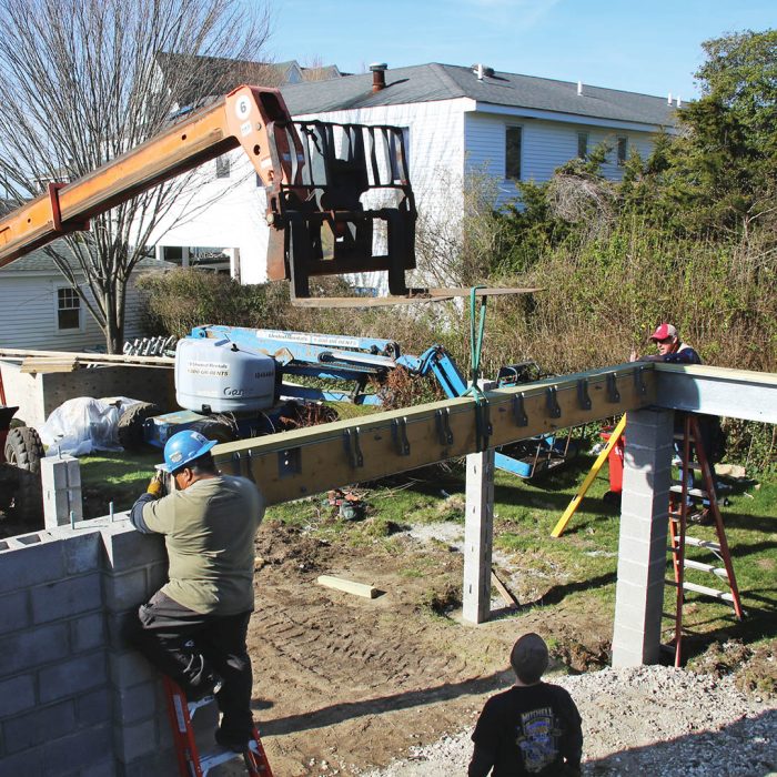
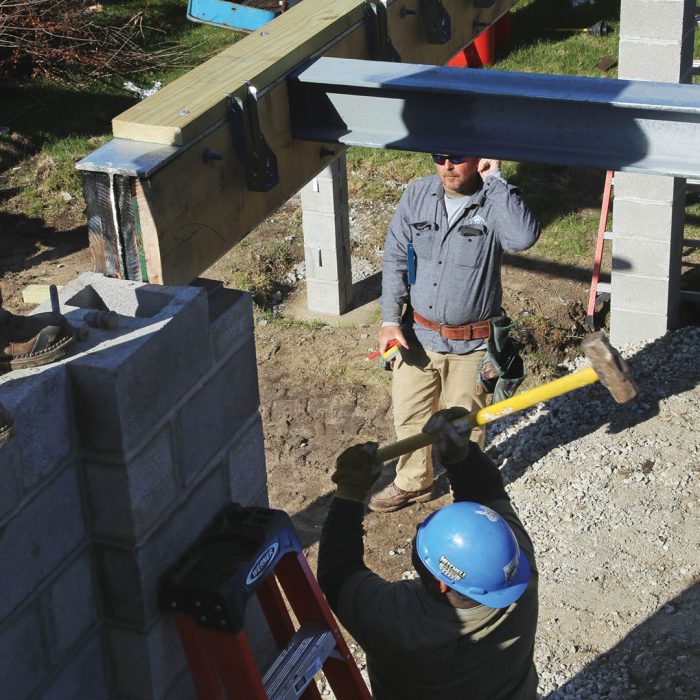
3.) Set the Other SideWith the beam’s web padded with lumber, the top flange plated, and the face-mounted hangers installed, the beam is lifted and guided in place by workers on both ends. Fully prepped, this beam weighs between 700 lb. and 750 lb. |
 |
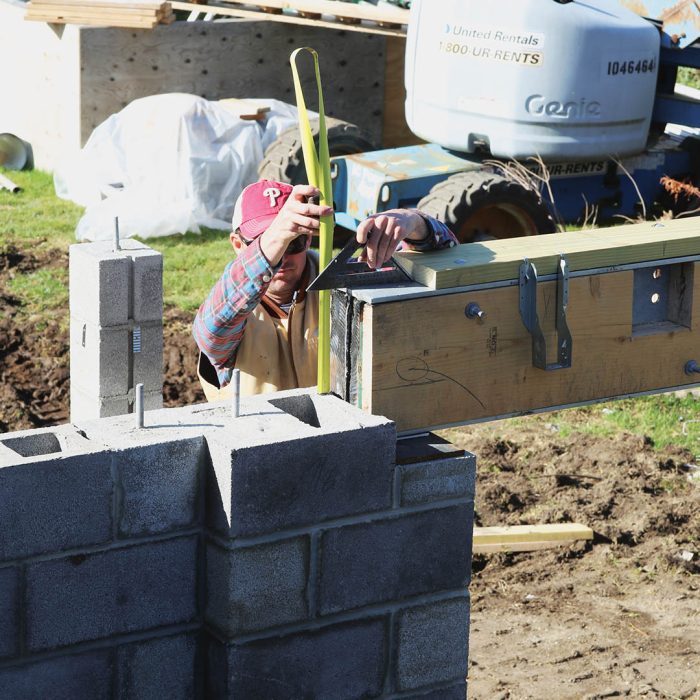 |
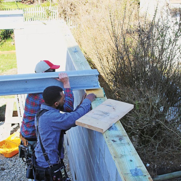
4.) Check the HeightThe top of the beam must be flush with the top of the floor framing. We check the height and then calculate the amount of steel shims needed to raise the beam so it will be flush with the top of the joists. The shimmed connection will be welded later. |
5.) Bring in Connecting BeamsThis steel beam parallel to the floor joists supports the first- and second-floor bedroom walls. Beam-to-beam connections are often bolted. The crew will hand-tighten the bolts on this end and then level the beam by shimming the other end. |
 |
 |
6.) Make it SquareOnce the steel components are in place, the corner is squared using the previously squared mudsills for reference before the I-joists are installed. Often brute force can move a beam, but sometimes one may need to be lifted slightly with a crane or all-terrain forklift. |
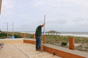
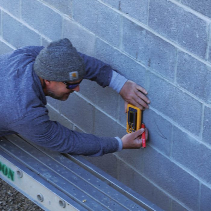
7.) Mark a Level LineWe use a rotating laser to establish a level reference line around the foundation. We measure from our reference line to the top of the beam and shim it to match the height of the bolted connection on the other end. |
 |
 |
8.) Shim to MatchThe height of steel components is often different from standard sizes of sawn lumber and engineered joists. The discrepancy may require adding shims, plates, or both to level the wood and steel elements. |
The architectural firm that designed this renovation project has their own engineering team that specified all of the steel-beam sizes, shear nailing, and structural connections. Other architects in my market use separate engineering firms for the same work. There doesn’t seem to be a big advantage to either arrangement, but in-house teams can usually answer questions and make changes with less back and forth between the architecture and engineering professionals.
Once you’ve worked with a specific design professional a few times, you start to notice their favorite structural solutions and connection details. The experience helps us more accurately estimate build time and cost. Around here steel fabricators familiar with residential wood-frame construction are pretty common, but if you can educate yourself as to how steel construction works, everything will go a bit smoother.
I recommend first learning how to interpret the steel descriptions in plans and catalogs so you can determine the dimensions of any specified beam, column, or channel. A basic understanding of how the components are bolted and welded together is also helpful. The steel fabrication shops I’ve worked with can drill and make other provisions for fastening wood components to the steel. Take advantage of these options, which make integrating steel beams and columns into typical wood-frame construction much easier.
Sturdy connections where different parts of the house come together are critical for the house to withstand the stress of high winds and water. The engineer and architect specify the connection details. The steel subcontractor and our framing crew build to the plans, and the local inspector checks the work as part of the framing inspection.
1.) Secure the MudsillsThe anchor bolts have 2-in.-square washers to prevent the bolts from pulling through the mudsill with high winds or flood water. This foundation was within 1⁄8 in. of square and level, so we were able to bolt the mudsills to the foundation without shims. |
 |
 |
2.) Make Bolted ConnectionsWhen the steel beams are in their final position, the bolts connecting steel components are fully tightened. Once a bolt is sufficiently tight, the electric wrench snaps off the end of the bolt as a visual indicator that the bolt has been tightened. |
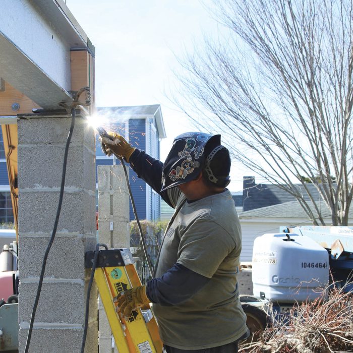
3.) Make Welded ConnectionsThe I-beams and any shims under the beams are welded to the embed plates by the steel crew using an arc welder. Once welded, the joints are cleaned of welding slag and then sprayed with a corrosion-resistant primer to prevent rust. |
 |
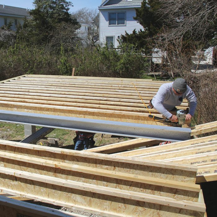 |
4.) Install Joists14-in.-deep I-joists span a little over 16 ft. from the masonry wall to the I-beam that receives them. The joists are nailed with 2-1⁄2-in. nails through the bottom flange into the mudsill. The engineered rim board and wall sheathing will add additional strength to the connection of exterior walls, floor system, and mudsill. |
5.) Add Squash BlocksShort pieces of 2×6, often called squash blocks, transfer loads from roofs, floors, and walls around the floor system to the mudsill. The blocks are nailed to the top and bottom flanges with 8d common or 10d box nails. |
 |
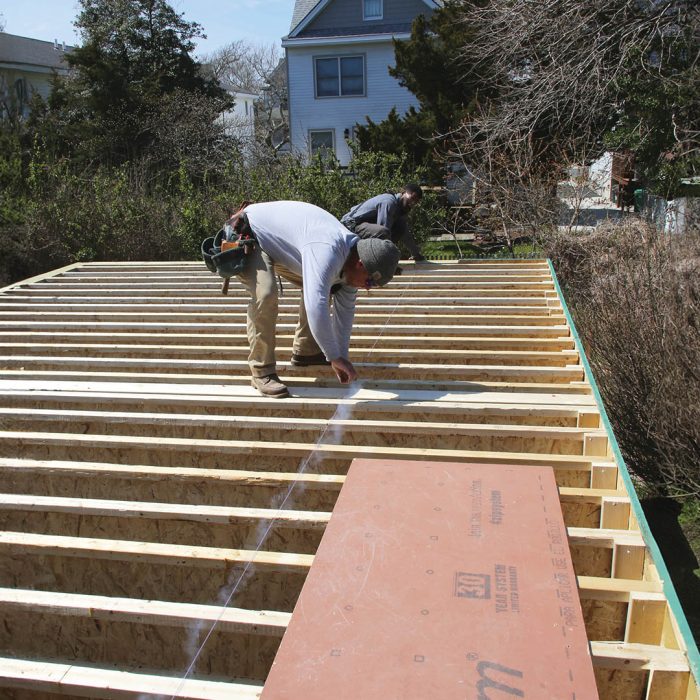 |
6.) Snap a Layout LineWe mark 4 ft. in from the outside edge of the engineered rim board on both ends of the addition and then snap a chalkline between the marks. The snapped line is where we align the interior edge of the subfloor. |
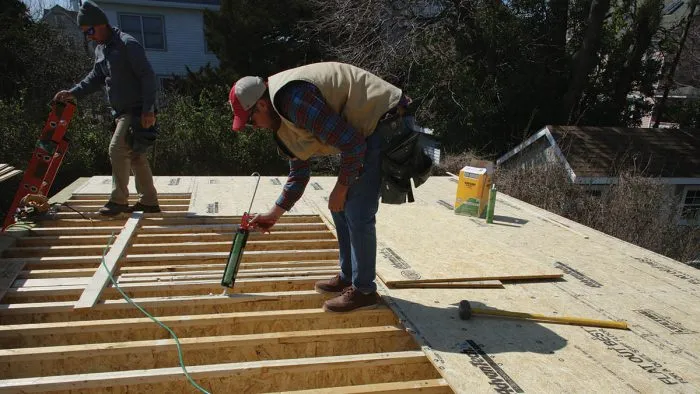
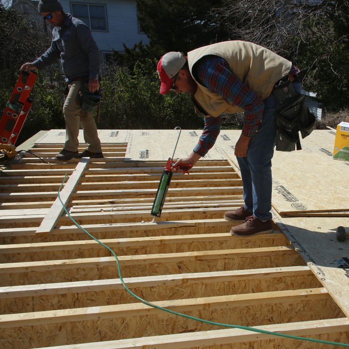
7.) Apply AdhesiveHigh-quality subfloor adhesive prevents squeaks and is critical for the floor’s strength, making it part of the floor system’s instructions. Using a 3⁄8-in. bead, we apply enough adhesive for a sheet or two of subfloor. Adhesive that has partially dried (skinned over) will compromise the bond. |
 |
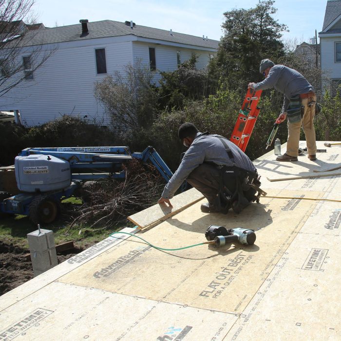 |
8.) Install the SubfloorStarting at the outside corner with the subfloor tongue toward the exterior, we install the subfloor in rows, working toward the other side of the addition. We stagger the seams by 4 ft. and nail the subfloor with 2-in. ring-shank nails every 8 in. |
If you’re a builder or designer hesitant to use steel because of a lack of experience, I’d say give it a try, as it’s not as different from engineered lumber as you might imagine. The big difference is that steel beams are smaller, making them easier to integrate into the rest of the building. I would also encourage anyone interested in ornate old buildings to come to Cape May for a visit.
Fiberglass is a common material for decks in my region of coastal New Jersey, especially when the deck is installed over living space, or when the client wants a porch roof that provides maximum protection from the weather. But when I talk to builders from other parts of the country, I find that this practice is almost unknown beyond the Jersey shore.
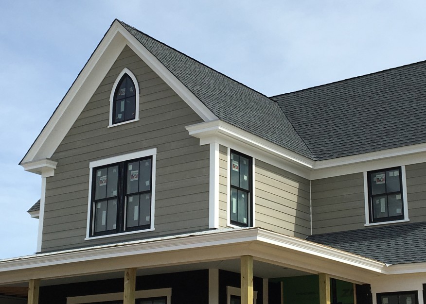
Cape May, N.J., has been a seaside resort since before the Victorian era, and the town has many homes in that period’s architectural style, along with examples of many other styles, as well. One feature that can be found in most of the older homes in this area is the crown-molding cornice. We see this detail on elaborate Victorians, traditional colonials, Greek revivals, and simple Capes.
When I’m framing a building with a long ridge span, I always prefer to set one long, straight ridge rather than fuss with multiple, shorter pieces of dimensional lumber in the traditional way. Recently, we framed a house that had two very long non-structural ridges—one just shy of 44 feet and the other nearly 46 feet long. I decided to make the ridge out of 1 3/4-inch-by-11 7/8-inch LVL. We lucked out because the longest length of that dimension LVL that was readily available locally was 48 feet. (You can special order longer lengths, but I would never delay a job for one ridge beam.) I ordered the lengths for both members about a foot longer than we needed.
In the last 10 years or so, cellular PVC products have been a game changer for exterior trim. Like most products, PVC trim has advantages and disadvantages. As a carpenter, I don’t love the material—I much prefer wood sawdust to plastic sawdust. And so does my wife—especially when I come home after working and the fine, white dust statically clinging to my clothing eventually finds our furniture. But dust notwithstanding, you can’t beat PVC for its longevity and stability.
Cape May County on the coast of New Jersey is a low place. Its highest point, in fact, may be the local landfill. Geologically, it was about as far south as the glaciers traveled in the last ice age. We don’t have rock and clay, like they have in Pennsylvania to our north and west, and we don’t have the stony glacial till that’s found in New England. But we do have very nice beach sand and lots of it. This sand makes a pretty good base to build on—until it gets washed out.
Most of the houses that my company builds are on the barrier islands of southern New Jersey, and most of those homes sit on grade-beams or footings supported by wood pilings or piers. These foundations are used in different configurations in many parts of the country to support buildings where soil conditions may be suspect. Here on the coast, the soil is typically sandy and low-lying. Coastal storms in these areas bring tidal surges and breaking waves that can wash away the sandy soil in a blink. Pier-and-beam foundations (see illustration, next page) ensure that buildings are properly supported and anchored on building lots that are just a few feet above sea level.